
|
Rigging Scale Model BiplanesBy John Seaman
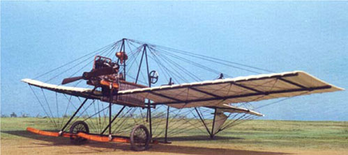
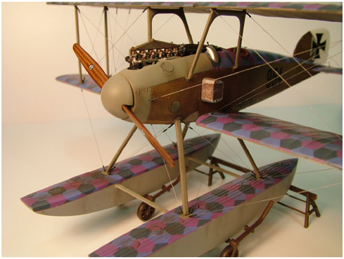
In this article I am going to tell you about four techniques I use to rig biplane models. One is well known, while the other three extend that standard method in a way that I think is new. I’ll summarize these techniques after some general comments, and a few notes about tools and materials. Most biplanes of all eras used some form of interplane rigging to provide strength, in addition to control cables to activate ailerons, rudders, and elevators — or in types like the Fokker Spinne (“Spider”) or the later Fokker E.III, to warp the entire wing. The former is illustrated very well by Robert Karr’s superb scratch-built 1/48 model, as seen below. (From an article originally appearing in the September 1999 issue of Internet Modeler and now available at the World War I Modeling site.)
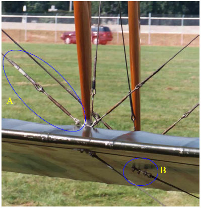
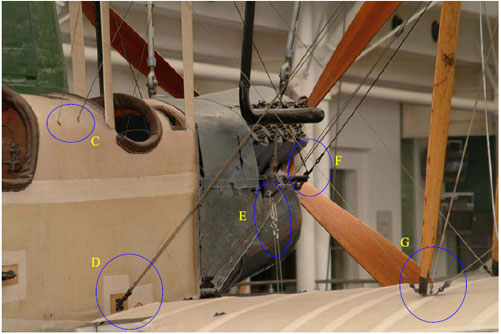
Bracing wires are like the standing rigging of a ship, while control lines are like running rigging. Aircraft modelers are sometimes reluctant to tackle biplane subjects because they are leery of reproducing the rigging that is necessary to achieve realistic results. I suspect that Fokker Dr.I’s and D.VII’s are modeling favorites, both because they are significant, colorful subjects, and because they require almost no rigging. Some recent biplane kits have offered convenient photo etch (PE) parts to ease the task of rigging. Tamiya’s Swordfish family, Accurate Miniature’s F3F family, and Fine Mold’s Kawasaki-built Type 95 fighter Ki-10-II, all in 1/48 scale, are examples of this approach. It will be interesting to see if Eduard’s forthcoming 1/48 Avia B-534 will have this option. Many biplane aircraft in the 1930’s used interplane rigging with a streamline cross section, so the “flat” photo etch used in these kits is appropriate. I’ve built the Swordfish and an F3F and found the PE very easy to install. In the absence of PE alternatives, one must choose a rigging material and proceed from scratch. The methods I want to share with you ease this process somewhat. Because of the materials I’ve chosen, my approach is most appropriate for 1/48 scale aircraft or larger. My technique is relatively easy to implement, yields very durable rigging, and allows a varying level of detail to be applied. I shall emphasize the creation of turnbuckles in what follows, both because in 1/48 scale or larger they are clearly visible, and because one of the methods I use to create them actually provides a way of tensioning the rigging—like the real things! In the photos below you can see something of the variety of turnbuckles and related hardware found on biplanes. I’ll refer to the lettered items later.
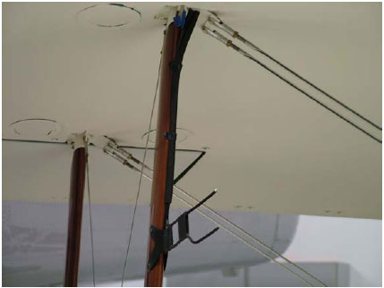
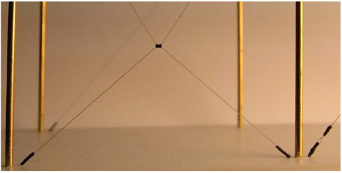
General Notes It is helpful to spend time looking at real rigging, turnbuckles, and associated hardware. Photographic resources are readily available on the internet. One of the best sites is the W.W.I Modeling Page. Full-size replicas and restorations are another source, although biplanes are not the dominate type in museums within driving distance of central Texas, there are some to be seen. The Old Kingsbury Aerodrome houses a Bleriot Model XI (replica), a Canadian JN-4 “Canuck” (this is a Canadian “Jenny”), a Meyers OTW, and a Thomas-Morse Scout. At the Cavanaugh Flight Museum in Addison you will find a Sopwith Camel, a Fokker Dr. I, a Fokker D.VII (all replicas), an N2S-1 Stearman, and a de Haviland Tiger Moth. The Lone Star Flight Museum in Galveston has a Grumman F3F-2 rebuilt from wreckage recovered in Hawaii. Closest of all is the PT-17 Stearman in San Marcos with the Central Texas wing of the Commemorative Air Force. All of these museums maintain websites, so Google away! Make sure you have good references before you begin a model rigging project. The box art sometimes helps, but is rarely sufficient. Instructions do not always contain a rigging diagram and when they do, attachment points and other details may not be represented. Windsock Datafiles are the gold standard for such references, although publications by Kagero and JaPo have recently come to the fore. Supplies and Tools Modelers use a variety of materials for rigging. I prefer nylon monofilament thread in 0.004” or 0.005” diameters. Fly tying monofilament is the same thing. I have used Danville’s Ultra Fine (0.004”) or fine (0.006”), for example. Some modelers swear by Aeroclub stretch thread or its equivalent. This is a Lycra thread, if I’m not mistaken, and is quite flexible. Lycra thread is also available from sewing supply sources, but a bit harder to find than monofilament. Brass wire such as the 0.006” diameter Detail Associates brand can be used. (If you use wire, you may need to straighten it. Do this by rolling the wire between a steel rule and a hard, flat surface, such as a small anvil, a tile, or a piece of glass.) Finally, there is good old stretched sprue. Photo etch companies like Eduard, Tom’s Modelworks, Part, and others provide scale rigging hardware. PE turnbuckles don’t look realistic to me because they are flat, but they could be “thickened” with paint or cyanoacrylate (CA) “super” glue. Model railroad turnbuckles, like those in 1/87 (HO) scale by Tichy Train Group, have their uses too. For example. see E in the BE2c photo. I make my own turnbuckles using micro tubing for fly tying such as Stalcup’s Hairline brand. I have never seen anyone else use this tubing, but it has worked well for me. There are three diameters that I know of: Micro, Midge, and Standard. All are listed in the Cabela’s catalog (See “Stalcup’s Tubing”). You can order it online from Cabela’s or at www.americanflyfishing.com. You can get this in a variety of colors. It has many uses in modeling, including couplings in plumbing like brake lines and insulators for radio aerials. Even smaller diameter tubing is available from McMaster-Carr at www.mcmaster.com. They have tubing made from a variety of materials. Small diameter tubing has many uses in modeling, including couplings used in plumbing like brake lines and insulators for radio aerials. I use several tools and adhesives in rigging biplanes. Since I prefer to use monofilament, I attach all lines with CA. You need to be adept at precise placement of very small drops of CA. This can be done with a sharpened toothpick, for example. I also have a needle inserted into an old paintbrush handle for placement of even smaller amounts of glue. ZAP seems to work best for me (regular—not extra thin or extra thick, “Slo Zap”). It is essential to have CA accelerator as well, such as Zip Kicker. A very sharp pair of tweezers is an absolute necessity. I prefer the type with curved ends called “curved watchmaker's tweezers”. I also use a pair of reverse action or “cross” tweezers. I have a pair of very small, sharp scissors as well as flush cutting nippers that I use to trim excess monofilament. I use dividers for measurement, along with a steel rule, such as General’s “Ultra Rule”. This thin, flexible rule has holes for precise marking. Fine drill bits with a good handle are a necessity. I use bits of size 77 to 84. These small drill bits are fragile and you will break them eventually, so it is best to have several spares. To start your holes, use a needle in a pin vice or similar tool as a punch. Biplane rigging requires plenty of light and a good pair of magnifiers. I could not work without my Optivisor. It is good to have a white tile or piece of white styrene to work over when manipulating monofilament and micro tubing. This makes it much easier to see the thin line and tiny pieces of tubing that make up turnbuckles. Tips on Using Monofilament and Micro Tubing Monofilament in 0.004” or 0.005” diameters is extremely fine—finer than a human hair. I’m not sure, but I wouldn’t be surprised if it is actually sub-scale for 1/48 aircraft. However, when painted silver, it looks appropriately thick to my eye. I prefer monofilament to stretch thread (Aeroclub or Lycra elastic knitting thread) precisely because it does not stretch. I want my rigging to do the job it does on the real thing—lend strength to the assembly. Monofilament is sufficiently elastic as to resist damage but allows tension to be applied. This means that monofilament can be used to align wings that are not quite parallel, for example. Monofilament and micro tubing both cut very easily with a hobby knife blade or scalpel. Both are quite tough and resist tearing and breaking. In order to thread micro tubing with monofilament, I hold the filament between my left-hand thumb and forefinger (I am right-handed), with the end pointing up. I hold a piece of tubing with my curved tweezers and slide it down onto the end of the monofilament. Since both the monofilament and the micro tubing are made of vinyl, they slide together very easily. This is easier than it sounds but you do need steady hands. I paint monofilament with thin acrylic silver or aluminum paint after installation. Lightly load a round brush with the paint and pass the line within the bristles. Some people like to paint the line before installation. A silver permanent marker is handy for this; just pass the line over the tip. Micro tubing takes acrylic paint well but you should paint it after installation—it will shed paint quickly if handled. I paint the finished turnbuckles a medium gray after installation. Two of the methods I will show you require drilling a tiny hole completely through the lower wing to receive one end of the rigging line. Since I install rigging after painting and most decaling, this means a little touch up paint is required to hide the hole. On the underside of the lower wing, decals will often cover the hole. If your finish is flat, be sure to brush a little clear flat over any spots of CA on any attachment point to avoid tell-tale shiny spots. Some aircraft types, like the Sopwith Camel or the Bristol Fighter, have doubled bracing wires. This is illustrated in the photo below of a replica Sopwith Camel at the Cavanaugh Museum in Addison. The methods described below can be used to produce doubled wires by carefully marking and drilling pairs of holes instead of single holes as described. This requires precise measurement in order for the lines to run parallel. I recommend using the General “Ultra Rule” for this. Its integral marking slots allow very precise alignment of holes for rigging.
OK, here are the methods. The first is well known. The others are variations on that approach. I’ll describe them in simple lists of basic steps. Letters in parentheses refer to the rigging example photographs mentioned earlier. They indicate that the method is ideally suited for that type of rigging and attachment. Method 1: Simple Method (C)
Method 2: Simple Method with Turnbuckles (B, D, G)
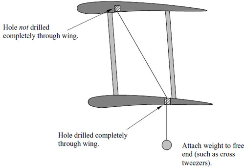
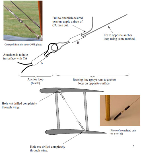
Method 3: Double loop method (A, F)
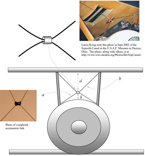
Method 4: Asymmetric Rigging
There are, of course, other methods for making turnbuckles. Two good tutorials are located at www.wwi-models.org/misc/Make_Turnbuckle.jpg and http://wwi-cookup.com/albatros/modelling_hints/kittech_turnbuckles.html. Now, no more excuses! Go build a biplane! Additional illustrations:
|

© Copyright 2010, Austin Scale Modelers Society (ASMS)